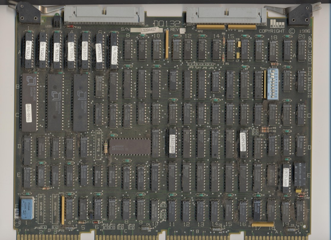
The DQ132 is a "Pertec formatted" tape controller for Q-bus systems, it works in both 18 bit (PDP-11/03) and 22 bit (PDP-11/23 etc and MicroVAX) backplanes. If you click on the labeled picture below it will show you a larger (more legible) version of the board. It emulates the DEC TS11 interface and can talk to the DEC TSV05 (very slow tape drive) drive or the TU80 9-track drive. It will also talk to any other Pertec compatible tape drive (generally these are 9 track reel-to-reel drives). It is supported by RT-11, RSX-11M, VMS, and NetBSD. It supports 800, 1600, 3200, and 6250 (GCR) densities.
NOTE: The following information on jumpers and configuration was provided by Dilog Corporation Customer support and is reproduced with their permission. The information and contents are copyrighted by Dilog Corporation and is provided for the personal use of the reader. You may not resell this information to anyone.
The image below identifies the locations of the configuration jumpers and switches:
 The
factory defaults for this board are shown on the right.
The
factory defaults for this board are shown on the right.
All of the jumpers (except for JP9 positions B and C) are shipped from the factory with a trace between them.
Controller Address Select
The controller address is selected using jumper positions JP1 and JP2. You need this if you already have a TS11 installed and this is the second (or third or fourth) controller on the bus. The default has the controller TSDB/TSDA (CSR) at 772520 and the TSSR at 772552 (all numbers in octal) for logical unit zero. Other possibilities are shown below:
|
Register Addresses |
Logical |
JP2 |
JP1 |
|
|
TSDB/TSDA |
TSSR |
|||
| 772520 | 772522 | 0 |
YES |
YES |
| 772524 | 772526 | 1 | ||
| 772530 | 772532 | 2 | ||
| 772534 | 772536 | 3 | ||
| 772720 | 772722 | 0 |
YES |
NO |
| 772724 | 772726 | 1 | ||
| 772730 | 772732 | 2 | ||
| 772734 | 772736 | 3 | ||
| 777360 | 777362 | 0 |
NO |
YES |
| 777364 | 777366 | 1 | ||
| 777370 | 777372 | 2 | ||
| 777374 | 777376 | 3 | ||
| 777420 | 777422 | 0 |
NO |
NO |
| Only one drive permitted at this address | ||||
Interrupt Priority Level Select
Jumpers JP3, JP4, and JP5 permit the interrupt priority level to be changed. The following table shows the possible settings. Note if you change the interrupt priority from the default you really should remove all the jumpers and then change it from the front. That way it won't like the priority is set one way when in fact it is set differently. On my board these jumpers had wrap posts installed in them and wire-wrap wire to select the level.
| Jumper Configuration |
Interrupt |
||
| JP3 | JP4 | JP5 | |
| IN | IN | IN |
LEVEL 4 |
| OUT | IN | IN | LEVEL 5 |
| IN | OUT | IN | LEVEL 6 |
| IN | OUT | OUT | LEVEL 7 |
Tape Drive Density and Speed Selection
The density and speed of the tape drive is selected manually at the drive unit.
Interrupt Vector, Extended Features, and Drive Quantity Select
The switch pack on the DQ132 controls features that you will probably change most often these include the interrupt vector, 18/22 bit addressing, and the drive quantity.
Switches S1 through S7 select the starting address of an interrupt vector for logical units 1, 2, and 3.
|
INTERRUPT VECTOR |
|||||||
| Switch # | 1 | 2 | 3 | 4 | 5 | 6 | 7 |
| Bit Position | 8 | 7 | 6 | 5 | 4 | 3 | 2 |
| Standard1 | ON | OFF | OFF | ON | ON | ON | ON |
| Octal | 3 | 0 | 0 | ||||
| 1Standard
switch settings show start of floating vectors, switch off sets a "1" bit. The last two bits are always zero. |
|||||||
The interrupt vector of logical unit 0 is fixed at 2248 by the prom. If only one unit is connected to the controller then switches 1 through 7 need not be set to any specific address, however logical units 1, 2, and 3 will get their interrupt vectors as follows:
Logical unit 1 - Switch settings (shown as 3008
in the table)
Logical unit 2 - Switches + 4 (ie 3048 in this table)
Logical unit 3 - Switches + 8 (ie 3108 in this table)
Switch 8 specifies 18 or 22 bit addressing. According to my copy of the manual only the TSV05 software handler supports 22 bit addressing on the Q-bus, not the TU11/TU80 handler. The default setting for this switch is "on" (ie use 18 bit addresses). If you are running this in a MicroVAX you will probably want to set this to "off."
Switches S9 and S10 set the number of logical units that are connected to the card. The settings break down as follows:
| S9 | S10 | Number of Logical Units |
|---|---|---|
| ON | ON | 1 |
| ON | OFF | 2 |
| OFF | ON | 3 |
| OFF | OFF | 4 |
Compatibility with Q/Q and Q/CD backplanes
Jumpers JP11 through JP16 are used to connect the card edge fingers on the C/D side of the card. JP11 and JP12 perform the function of an M9047 bus grant card, JP13 thru JP16 connect additional grounds (on Q/Q backplanes) to the board for better noise rejection. If the card is to be installed in a Q/Q slot all jumpers should be installed (default) and if it is to be installed in a Q/CD slot all jumpers should be removed.