Project #5: Multi-digit counting display
| Counting in HEX was easy, counting in decimal is
a bit trickier. Plus we've got a new gizmo to play with, an 8 digit
multiplexed LED display.
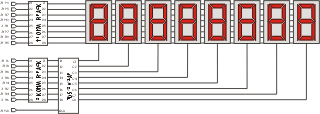
The schematic on the right is the display I built for this project (click it for a larger view). The display multiplexes 8 seven segment displays on one set of display driver lines. |
When the display is rapidly scanned using the FPGA it appears to your eye as if all of the digits are lit simultaneously. Further, it saves FPGA resources since you only consume 16 I/O lines (same as the BEDLED board) but get eight digits to play with.
Like a good developer I'm reusing all of the previous projects in this one, that's right the looper too. But it turns out it may not be the best solution.
Of course things never turn out as you would expect, otherwise you wouldn't really be learning anything now would you? One of the twists in this project was that I designed the multi-digit board and then wrote the VHDL code to drive it. When I first tried it out the displays were way too dim (you couldn't read them with the lights on!). As it turns out I had failed to consider the voltage dropping potential of the green LEDs and the NPN current sinks in my current limiting resistor calculation. So I had 180 ohm resistors and was just barely turning on the LEDs! I measured the voltage (about .6 volts across them) and came up with the 47 ohm values. This made the display much brighter (nearly acceptable actually.) However, it is plenty bright when showing 1, 2, even 4 digits, but gets less bright showing 8. This is due to the 'duty cycle' effect of only turning on the LED for 1/8th of the total refresh time. If I redesign the board I'll use the additional 2 I/Os that are available on the plug on connector and make it a dual 4 digit display. That way I need only mux 4 digits at a time and the display would be fine.
I also got to learn about about how precedence affects things in VHDL designs. In particular, the 'TEST' input pin was lower precedence than the 'BLANK' pin, thus when blanking leading zeros my initial design would only light up in test mode those digits that had non-zero contents. That was fixable in the HEX_DISPLAY module.
Leading zero suppression and decimal support were also both interesting. This design hard codes the decimal point between digits 7 and 8. Then the leading zero suppression code in COUNTER makes sure it will neve suppress the last two digits. However, it should be possible to do this in the MUXDISP module and have it work automatically so that leading zero suppression only occurs on the digit to the immediate left of the decimal point.
I did get a great display out of this project and I'm looking forward to using it on the next one, the mouse port. As I actually assembled two 8 digit displays I should be able to have the X and Y co-ordinates of the mouse display in real time on the two displays. Hmmm, maybe I'll have to support negative numbers after all.
| Next Project | ||
|
|
||
