Introduction
This project was inspired by a circuit that a friend of mine, Simon Field, over at Scitoys.com showed me. He had built a very simple transmitter circuit out of a 1Mhz "can" oscillator and a serial connector (see it here) In his circuit he used a computer to turn the transmitter on and off and to send Morse code.
In the United States (and possibly elsewhere) there is a custom at Easter to hide Easter eggs so that the children can search for them. While some of the eggs may in fact be the spawn of chickens, most of the time they are egg shaped plastic carriers into which candy is placed. The kids find the eggs, they extract the candy, and then the kids run around at supersonic velocity on a sugar high all afternoon. Of course sometimes the Easter Bunny forgets where he hid the eggs. Technology to the rescue!
This project is an "Emergency Egg Locator Beacon" or EELB for short. The EELB is so small it could easily be embedded in a plastic Easter egg with room left over for candy treats. It emits a customizable message on the AM band that can be picked up by any transistor AM radio, and with simple radio direction finding (RDF) techniques anyone can locate the missing eggs.
The Circuit
I was reading the datasheet for the PIC 12F6xx series of microprocessors and noticed that there was a clock mode that fed the system clock, divided by four, out one of the pins. The presumed used is for external synchronization but I had other ideas. Further, the 12F6xx series PICs have an internal oscillator that can run them at 4Mhz. So here we had a computer in an 8 pin dip that could put 1Mhz out on one of its pins. I couldn't pass that up.
Here is a schematic for the circuit. As you can see it is pretty simple.
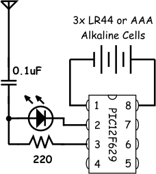
Figure 1: The EELB Circuit Diagram
The PIC is configured to generate a 1Mhz output on CLKOUT. (pin 3 in the datasheet). That pin drives a 220 ohm resistor which is connected to an LED that is then "grounded" by pin 2. A capacitor is tied to the anode of the LED (more about that in a minute) and a length of wire is hung off the capacitor (the longer the better, up to 1000' :-)
Theory of Operation
AM radios are based on the concept of a "carrier" or base frequency, that is modulated at audio frequencies. A simple diagram is shown below.
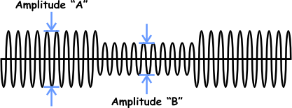
Figure 2: Amplitude
Modulation (AM) of a sine wave by a rectangular wave
In the figure a sine wave's amplitude is being modulated (changed) over time. If you were to filter out the base frequency you would be left with a simple rectangular waveform. This is exactly what an AM Radio Receiver does, it tunes a circuit to the carrier frequency, and then filters out the carrier leaving its change in amplitude as the signal you want.
So all we need to do in order to turn our PIC system into an EELB, is to produce a carrier wave and modulate it.
By setting the oscillator mode to INTOSC_CLKOUT in the configuration register, our PIC generates a 1Mhz clock on pin 3 of the package. Since 1Mhz is smack dab in the middle of the AM band it works out nicely for our carrier frequency.
To modulate the 1Mhz carrier the PIC is programmed to turn pin 2 (GPIO 5) on and off. When pin 2 is on, the LED is reverse biased and does not turn on. Consequently the output of pin 3 and the anode of the LED, goes from 0v to Vdd at a frequency of 1Mhz. However, when pin 2 is switched off the cathode of the LED is grounded. Now the voltage at the anode is simply the forward voltage drop of the diode, or about 2.1V for a red LED. In this way the amplitude of the 1Mhz clock out signal can be modulated between 5V and 2.1V by changing the state of pin 2.
The capacitor isolates the antenna from the LED and the PIC pins.
Writing the Software
The software for this project is also pretty straightforward. The 12F6xx has an 8 bit timer with a settable pre-scaler. The timer creates an interrupt whenever it overflows. The software initializes the timer with a prescaler of 8 and preloads it with a value of 133 so that it will interrupt approximately once every millisecond.
During the interrupt service routine, the number of interrupts are counted and once 100 of them have been seen (or .1 seconds), the interrupt routine sets a flag to tell the main program that .1 seconds has gone by. The other thing the interrupt service routine does is to toggle the state of pin 2 depending on whether or not the PIC is sending a logic 1 or a logic 0.
The toggling of pin 2 at a rate of 1mS causes the 1Mhz carrier wave to be modulated by a 500Hz square wave. 500Hz is slightly below "high C" in the musical scale (which is 524 Hz). Thus when a logic 1 is being sent the radio receiver plays a tone, when a zero is being sent only the carrier frequency is present.
Now to get Morse code out of this thing I used the ratio between "dits" and "dahs" of 3:1. This is established by custom that a dash in the code is approximately three times longer than a dot. By shifting a bit stream serially through the register that the interrupt service routine is using to determine tone or no tone, presents to the listener very recognizable code.
A complete listing of the software is here.
Going Further
A couple of ways to go further with this project are miniaturization and actual telemetry.
The PIC16F625 version of this chip has four 10-bit A/D converters. It would be an interesting exercise to hook one or two of those A/D converters up to temperature or light sensors and have the egg broadcast current lighting and temperature conditions where ever it is.
Another possibility is to use the PIC10F206 which comes in a 6 pin SOT-23 form factor. This chip and LED and resistor would fit on a circuit board that is smaller than the 8 pin DIP used in this project. The 10F200 doesn't have EEPROM data so either the message would have to always be programmed in, or an external EEPROM like the Dallas "one-wire" parts could be used.
Finally, the EELB simply repeats its message, again and again. One upgrade to the software would be to cause the PIC to enter sleep mode for several seconds before transmitting again. Now this isn't essential as the entire project draws in the neighborhood of 3 - 4 mA of current so it will run for days on three button cells. However sleep mode would let it run for months.
--Chuck McManis