The Handyboard by Dr. Fred Martin
The Handyboard
The lighting one is sub-optimal. At some point I need to re-shoot all the images in a studio or something instead of on my desk.
The Handyboard has its own web site where various folks have contributed to its design. I wrote a C library for it so that I could program it using ICC11 from ImageCraft.
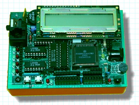
The Handyboard like the Miniboard and 6.270 board use the Motorola M68HC11 high-integration micro-processor running at 8Mhz. Because the 6811 has a 4 phase clock the "E" clock on the processor is 2Mhz. The Handyboard has four motor ports and 16 "i/o" ports. Of these 8 are analog or digital and 8 are digital only. All but two are inputs basically.
There is also a 40Khz oscillator and an IR detector circuit based on the Sharp IU-60 detector (seen in the lower right corner).
This controller has 32KB of battery backed up static ram (and 512 of EEPROM in the CPU).
Perhaps the weirdest thing about this design is that the CPU runs in "Special Test Mode" all the time. The salient feature of this mode is that the chip can switch from "expanded" into "compact" mode at will. Fred used this to share the RAM address and data lines with the LCD interface.