Looper Project Solution
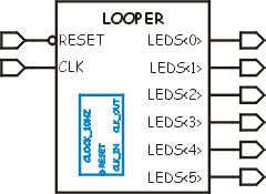
| This is the solution I came up with for the
Looper project. The schematic representation of the circuit is on the
right (sort of.) The symbol is trying
to show you the inputs and outputs and the fact that CLOCK_10HZ is
embedded inside. Perhaps after I'm better at this I'll redo it.
The specification for this part is to take a 24Mhz input clock and sequentially light up each LED at 100mS intervals. The CLOCK_10HZ component provides the 10hz count and then this VHDL provides an endlessly rotating shift register. Things I learned from this step:
|
 |
VHDL Source code for the LOOPER
-- Looper.vhd					Chuck McManis 10-Mar-2001
--
-- This then is another trivial project that instantiates project 1 (the
-- clock generator) as a component in a device that displays a moving LED
-- segment on a seven segment display.
--
library IEEE;
use IEEE.STD_LOGIC_1164.ALL;
use IEEE.STD_LOGIC_ARITH.ALL;
use IEEE.STD_LOGIC_UNSIGNED.ALL;

entity looper is
    Port ( leds : out std_logic_vector(5 downto 0);
           clk : in std_logic;
           reset : in std_logic);
end looper;

architecture behavioral of looper is

    -- Declare a "component" which can then be used in the design
    component clock_10hz port (
	clk_in, reset : in std_logic; clk_out : out std_logic	);
    end component;

    -- end component declaration

    signal time_clk : std_logic;
    signal ring : std_logic_vector(5 downto 0);

begin

    -- Instantiate an instance of the component and connect it up to signals
    clock: clock_10hz port map ( clk_in => clk, clk_out => time_clk, reset => reset);

    -- This process is sensitive to the output of the clock generator rather than
    -- the clock input to the circuit.
    rotate: process (time_clk, reset) is
    begin
	if (reset = '0') then
	    ring <= "000001";
	elsif rising_edge(time_clk) then
	    -- This neat trick does a rotate left, remember that it works because
	    -- the value in ring is the previous "phase" and we're setting what it
	    -- will be for the next phase.
	    ring <= ring(4 downto 0) & ring(5);
	end if;
    end process;

    leds <= ring;

end behavioral;