Assembling the ServoGizmo
Checking the Parts List
When you get your kit there should be a piece of paper included that lists all of the parts included in the kit, this should be identical to the list at the end of this document unless the board has been revved. You should go through the parts and check off each one to be sure everything is present and identified. The .01uf monolithic capacitors will be marked '103 K'.
DO NOT take either the Integrated circuits off their protective static containers until just before you use them. Ideally, you should also keep yourself grounded whenever you handle static sensitive parts. In general it is sufficient to touch something that is grounded before you pick up a part.
Some substitutions that you can make if you are ordering parts:
- 100v electrolytic versus 50v electrolytic caps
- 1N4148 vs 1N914 signal diode.
- Conformal Resistor packages vs dipped epoxy resistor packs.
- L293D instead of the TI755410
- Other LED's as long as they are no wider than 1.8 mm.
- LM7805 regulator (higher drop out voltage though!)
Some other Notes
Some of the items in the kit are polarized. This means that they must be installed with the correct orientation. The parts that are polarized are the electrolytic and tantalum capacitors (marked with a + on one lead), the diode (marked with a band on one end), the two resistor packs (marked with a dot on the end), the LEDs, and the integrated circuits. When you install the integrated circuit sockets be sure and orient the socket correctly (line up the notch shape with the silkscreen) so that it will guide you when installing the ICs.
The diode and the transistors are heat sensitive. This means that if you hold the soldering iron on them too long you can damage them. My recommendation is that you count "one one thousand, two one thousand, etc" and if you get to "seven one thousand" and you haven't successfully created the joint you stop. Wait 10 or 20 seconds for the part to cool and try again. This is particularly difficult on the areas where there are really wide traces because the copper foil absorbs the heat.
Assembling the Servo Gizmo Board
The following steps will take you through the assembly of the Servo Gizmo board. Read through all of the steps first, then follow them in order when you assemble the board. The assembly steps attempt to build up the board by "levels", that is putting equal height components in at the same time so that the board doesn't rock and tilt on your work surface while building it. On some of the steps you will see a warning sign, this sign indicates that the components being installed in that step must be installed in a specific orientation.
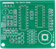
Below is a picture of the unpopulated board. The board is bordered by a sequence of letters and numbers. The letters and numbers are used to identify specific locations on the board using a notation of the form B,3. This location would be column B, row 3 on the board. Similarly the location B,1.5 would be column B, between rows 1 and 2. Whereas the location B,2-4 indicates a location in column B that spans rows 2, 3, and 4.
|
|
A | B | C | D | ||
| 1 |
|
1 | ||||
| 2 | 2 | |||||
| 3 | 3 | |||||
| 4 | 4 | |||||
| A | B | C | D | |||
| Figure 1: The Servo Gizmo Board | ||||||
|
|
Locate the Servo Gizmo board, its shown above in figure
1, and install the two IC sockets (18 pin and 16 pin) and
optionally a 3 pin SIP socket for the ceramic resonator at C,2. Note that the IC sockets have a notch that should line up with the silkscreen notch. Turn the board over and solder them. I find a bit of tape (masking tape) will hold them to the board while I'm flipping it over. |
|
|
|
Locate the small signal diode and install it. It installs in the position A,3. Watch the orientation to make sure the band faces to the "top." (away from the mounting hole) | |
|
|
Install all of the 1/8 watt resistors:
|
|
|
|
Install the 47K resistor pack at location B,1-3. Watch the orientation of the resistor pack. The pin one "dot" or "line" indication should face toward the voltage regulator. | |
|
|
Install the right angle connectors for J1, J2, and J3 at A,2 A,3 and D,1-3 | |
|
|
Install the LEDs in locations B,3-4. The green is the bottom LED (PWR) and the two next to it are Amber. Watch the orientation If you're using the Panasonic LEDs the barely perceptible flat side faces "down" toward B,4. The cathode for all of them goes to the left hand hole. | |
|
|
Install the two PN3904 transistors at location A,4 and B,4. Watch the orientation and line up the flat side of the transistor with the silk screen. | |
|
|
Install the 2x2 header in location A,2.5 Again some tape will help hold it close to the board while you solder. | |
|
|
Decide if you're going to supply 5V to the Servo connector. If you are then solder a piece of wire between the pads at A,2 below the capacitors. If not leave those pads open. | |
|
|
Install the capacitors at A-1.5 Watch the orientation there should be a plus on one of the pins (or a -) In both cases the minus side is the lower pin. | |
|
|
Install the ceramic resonator at location C-2 if you did not install a 3 pin SIP header. Note that this part is sensitive to heat so do not spend more than a few seconds soldering it. | |
|
|
Install the push button switch at location D-4. Watch the orientation as the flat side should be on the left. | |
|
|
Finally, install the voltage regulator. Watch the orientation and make sure the flat metal tab is on the side with the heavy white bar on the silk screen. |
Don't install the chips yet!!!
Testing and Checkout
Testing and checkout is fairly straight forward. First check your soldering to make sure there are no solder bridges (places where the solder has formed a short circuit between pads). When you are satisfied that things are soldered correctly. Apply at least 6V and less than 30V to the 8 Pin connector. The pins are numbered from the top down.
Pin 4 - Battery Minus (Ground)
Pin 7 - Battery Plus (V+)
At this point if you get it wrong no harm is done, but later when the chips are in you can damage them. At this point the PWR LED should light. If it does not, disconnect power immediately and recheck your circuit. Possible problems are a solder bridge on the voltage regulator, the capacitors are installed backwards, or the LED is installed backwards.
Once you have the LED lighting up, check the power at pin 14 of the 18-pin (PIC) socket, and pin 16 of the 16-pin (Driver) socket. Both should read around 5V (4.9 - 5.1 are Ok).
Now program the PIC with this test program, and install it into the board.
Apply power and the board should blink the SIG LED at a rate of about 1 hz with a 4Mhz resonator (faster if you're resonator is higher frequency and slower if it is of a lower frequency). Pressing the button should cause the CAL LED to start blinking as well. If nothing is working, verify that the Amber LEDs are installed correctly, check that PIC chip is grounded (pin 5 of the 18-pin socket is soldered) and check to see that the resonator is oscillating (the easiest way to do this is with an oscilloscope connected to pin 16 or 15 of the PIC, you should see a fuzzy band of oscillation.
Once the LEDs are blinking, install the TI755410 (watch the orientation!) and connect a light bulb between pins 2 and 6 of the 8 pin connector. The light bulb should be varying in brightness, getting bright, going dim, getting bright, going dim. The rate will depend on your oscillator again.
That's it! Your ServoGizmo is fully operational and ready to take on the personality that you choose for it.
The parts list for the Gizmo can be found here.
A schematic for the Servo Gizmo can be found here. (Acrobat Reader Required)