December 30, 2001
PICs measuring pulses in the 1000 to 2000 uS range are of interest to me. This interest arises from the fact that it is this width of pulse that is produced by an R/C receiver when it is receiving a signal from a transmitter, this is the "servo output signal."
Now most PIC projects that deal with R/C servos are interested in generating a pulse because they are going to command R/C servos to do something. The most common use is to command servos that have been modified into gear motors. My most successful project, the PIC based ESC, was more interested in receiving the signal and interpreting it for PWM generation.
Microchip finally introduced an 18 pin PIC with the CCP unit (capture/compare/PWM). This is the 16F62x series. My favorite is the '628 since it also has a USART on chip. Given my interest, I set out to create a project to figure out if I could learn how to capture a pulse from an R/C receiver and measure it, then do something useful with it (like set output pins based on it.)
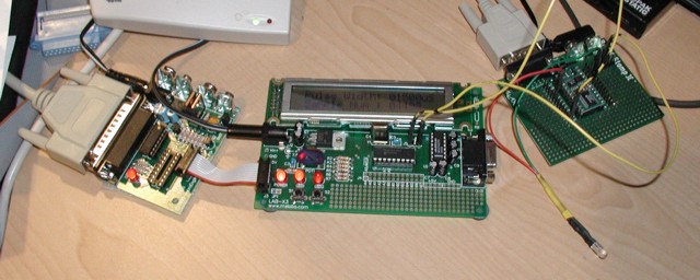
This project is designed to measure an incoming pulse with a LAB-X3 board that has been suitably modified, and display the result on its built-in LCD. The pulse in this particular example is being generated by a BASIC Stamp II.
The picture above is the setup used in this project. On the left is the EPIC programmer that is sold by microEngineering Labs, it is connected to the LAB-X3 board in the center, and connected to it by some jumpers is the BASIC Stamp II on the right. The BASIC Stamp II is connected back to my PC using a serial cable.
The program on the BS2 is simply this:
|
LOW
7 '
Make P7 logic 0 |
||
| Listing 1: BASIC Stamp Test Program |
As you can see this is generating a new pulse every 10 mS of 1500 uS. An interesting tidbit is that according to the BS2 docs, the second parameter for PULSOUT is the pulse width in 2uS increments. However, when I first ran this program on the BS2 and finally got my program working on the X3, the result was a pulse of 1496 uS, not 1500. So I upped the value by 2 and sure enough, 1500 on the nose. (sometimes 1501 but generally 1500).
 The
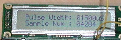
output on the X3 is shown to the right. The top line shows the pulse width and
the bottom line shows the number of samples that have been received. I slowed
it down so that I could get a picture with a stable number in the "sample
num" line.
The
output on the X3 is shown to the right. The top line shows the pulse width and
the bottom line shows the number of samples that have been received. I slowed
it down so that I could get a picture with a stable number in the "sample
num" line.
The PIC program is nearly entirely interrupt driven. The initialization section setups up the CCP1 unit with the code:
| BSF TRISB,3
; CCP1 is an input. BSF PIE1, CCP1IE ; Enable interrupts from CCP1 CLRF STATUS ; Back to BANK 0 MOVLW B'00000001' ; Enable Timer 1 1:1 Prescale MOVWF T1CON MOVLW B'00000101' ; Capture mode rising edge MOVWF CCP1CON BSF INTCON, PEIE ; Enable Peripheral Interrupts BSF INTCON, T0IE ; Enable Timer 0 to interrupt BCF INTCON, T0IF ; Reset flag that indicates interrupt BSF INTCON, GIE ; Enable interrupts |
||
| Listing 2: Interrupt Initialization Code |
The tricky bit is that you have to enable the PEIE bit and then watch for interrupts, and you have to have Timer1 running. Also its a good idea to clear the flags before you enable GIE as you will get an interrupt sometimes immediately if you don't.
When interrupts occur, it is processed with this code:
	;
        ; Process interrupts from the Input Capture/Compare pin
        ; (CCP1 on the 16F628)
        ;
ISR_1:
        BTFSS   PIR1, CCP1IF    ; Check to see that CCP1 interrupted
        GOTO    ISR_2           ; If not continue
        BCF     PIR1, CCP1IF    ; Re-enable it
        BTFSS   CCP1CON, CCP1M0 ; Check for falling edge watch
        GOTO    FALL_EDGE       ; Go pick up the falling edge
        MOVF    CCPR1L,W        ; else store leading edge value
        MOVWF   LEADING         ; into 16 bit word LEADING
        MOVF    CCPR1H,W
        MOVWF   LEADING+1
        BCF     CCP1CON, CCP1M0 ; Now capture the trailing edge
        GOTO    ISR_2           ; Exit the interrupt service routine

FALL_EDGE:
        BSF     CCP1CON, CCP1M0 ; Re-set for trailing edge capture
        MOVF    CCPR1L,W        ; Store the captured value into
        MOVWF   CAPTURE         ; CAPT_LO and ...
        MOVF    CCPR1H,W
        MOVWF   CAPTURE+1       ;             ... CAPT_HI
        ;
        ; 16 bit subtract
        ;     CAPTURE = CAPTURE - LEAD
        ;
        SUB16   CAPTURE, LEADING

        BSF     GOT_ONE,0       ; Indicate we have a new sample.
        MOVLW   I_CNT
        MOVWF   T0_COUNT
        INCF    COUNTER,F
        BTFSC   STATUS,Z
        INCF    COUNTER+1,F
|
||
| Listing 3: Interrupt Service Routine |
As you can see, when the leading edge comes in, the contents of the CCPR1L and CCPR1H registers are copied into temporary storage and the CCP unit is set to interrupt on the falling edge. Then when the falling edge arrives the values in CCPR1L and CCPR1H are copied out again, and the old values are subtracted from the new values, leaving the result in the 16 bit word CAPTURE.
The units of capture are microseconds because the basic clock (Fosc) is 4 Mhz, and Timer 1, the time base for the capture unit, is initialized with a prescaler of 1:1. You might think that would give it a .25uS resolution but in fact the internal clock on the PIC is Fosc/4 or one fourth the external clock. Thus Timer 1 ticks every microsecond and the result is in microseconds. If you need more resolution than this (I don't) then you can bump Fosc all the way up to 20Mhz which gives you a 5Mhz internal clock and .2 uS resolution on the input capture. Since Timer 1 is only 16 bits your limited to a max pulse width of 65,535 * units so in my case pulses over 65 mS would not read correctly.
The other interesting bit I implemented in this project was setting up Timer0 as a 20mS watch dog timer. If I haven't seen a pulse in 20mS I reset the capture value to 0. This bit of code lets me implement the full state machine for my electronic speed controller project in a lot more flexible way. I certainly considered it a success.