Making Plastic Wheels
July 21, 2002
My previous page gave a sense of what I was trying to accomplish. Unfortunately making the mold in haste lead to less than satisfactory wheels. So for my next go at it I changed two things:
First I created a new mold by putting a servo horn on a piece of aluminum tooling plate. This horn was attached with double stick foam tape.
Once I had the mold I made the wheel by cutting the bottom off a round plastic container and using that as the mold sides.
The results were better than the first time :-)
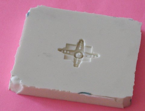
The new mold is shown below. This is a pretty big "chunk" of silicone RTV. It measures 4-1/2" x 4-1/8" and is approximately 1/2" thick. This limits me to wheels with a radius of 2".
You can see the impression the sticky tape made (the squarish indentation) that is around the servo horn. On "the final version" I won't use sticky tape and will instead make a better mold form but more on that later.
The next step was to get together
my wheel form, the A & B parts of the Alumilite and get ready to mold.
This is shown below.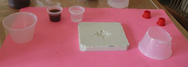
Identifying things from left to right, we have the plastic container I'm going to mix the Alumilite in. The A & B parts already measured into two small cups. The mold "bottom" with the servo horn impression in it. And the wheel form which is another container with the bottom cut off. At their "top" these containers are 3" wide so the resulting wheel will have a diameter of 3".
Now since I've only got two hands, I could not take a picture of myself mixing the A & B parts, then making sure the cup part was aligned and the pouring in the Alumilite and then holding it for 2 minutes while it cured. However once I could take my hand off it I did and took another picture and that is next:
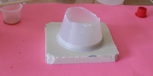
Pretty cool eh? Actually pretty hot! The curing reaction is exothermic and so when it starts curing the plastic gets up to something like 80 degrees C! However, with my 4 Tbsp (approximately) of material (2 each of parts A & B) you can see that I filled the bottom to a depth of about 3/8". This is easily twice as much thickness as I need so that gives me a better handle on how much material will be expended in making wheels that are 1/8 - 3/16" thick.
After four minutes you can touch this stuff without totally burning your fingers so I pulled off the cup and popped out my wheel.
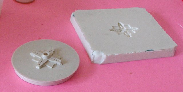
That looks much more like a wheel yes? However you will notice that the cup does not have vertical sides so the wheel's edges have a definite slant to them. Now the simplest way to eliminate that edge is to chuck the wheel into a lathe and turn it down to the point where its edge is perpendicular to its surface. Once there you could also cut a groove in the edge to hold an O-ring for a tire. Finally, the hole in the middle is drilled out to allow the servo mounting screw to pass through the wheel and your done. Presto, new wheel.
One of the cool things about this
technique is the detail that is picked up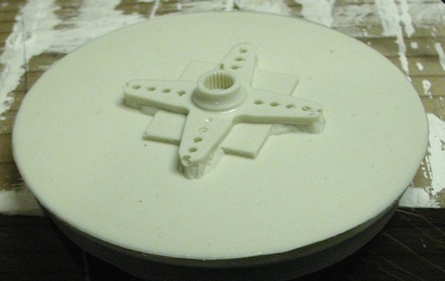 by the molding process. The picture on the right is a close up of the servo
horn as it appears on the wheel. If you click the image you get to a bigger
picture that allows you to see clearly the precise transfer of the servo
spline pattern to the wheel hub.
by the molding process. The picture on the right is a close up of the servo
horn as it appears on the wheel. If you click the image you get to a bigger
picture that allows you to see clearly the precise transfer of the servo
spline pattern to the wheel hub.
Ok so most of the concepts have been proven out and the next step is a true wheel molding jig. So the next time I create a mold there a couple of things I'm going to change.
The first is that I'm going to mill some concentric rings in the tooling plate that are spaced at known intervals from the center, and exactly aligned with the center. This will let me create a wheel form with a groove in it at that same diameter and not only will this force the wheel form to line up with the exact center of the mold but will also provide an O-ring type seal for the form. That will mean that pouring will always give a really nice wheel.
The second thing will be actual wheel forms. Milled out of 1/4" aluminum sheet, the wheel form should rest easily on the silicone, align with the alignment bump/ring. And have a "lip" milled into the edge so it leaves a wheel with a built in groove for putting a tire into. I suppose if I want to get truly fancy there could be another wheel form that is a bit wider than this one and that would allow you to cast/pour an RTV tire on to the wheel once you had made the wheel.
On second thought the wheel form cannot include the tire "bead" ring otherwise the wheel will be stuck in the wheel form, unless the wheel form is in two pieces and can be pulled apart to release the wheel, that would work....
The third thing will be alignment bumps spaced at an equal number of degrees around the mold. That and some disks with aligning notches, would let me create pre-made voids (think big spokes) that would lighten the overall weight of the wheel. These void units could be either simple cylinders or more complicated shapes to give more interesting wheels. If you use the "aluminum" or "copper" power additive with the Alumilite you can make nice metal rims this way.
One of the goals here would be to make wheels that were 3.8200" in diameter. "Why?" you might ask. The answer is that the circumference of such a wheel is very nearly exactly 12" thus one rotation of the wheel equals one foot of robot travel (assuming no slippage). It also makes it easy to compute how fast your robot will go, just take RPM and and divide by 60 to get feet per second.